Nintendo Switch: Joy-Con Shells & Buttons

As the COVID-19 pandemic continues to spread across the world, more and more folks have been ordered to stay indoors for an indefinite amount of time, imposing a social barrier and setting forth the challenge to maintain a tough balance of both psychological and physical well-being. As humans, we need to keep ourselves entertained to prevent our mental states from depreciating, whether it be binge-watching the entire Netflix archives or fighting waves of distressed living-room gamers for the so very limited stock of Nintendo Switch consoles. If you happened to be lucky (or desperate) enough to score a Nintendo Switch in the past few months, you may have come to form the same opinion on the stock Joy-Con and console shells as I have; they aren’t very pretty. Luckily there is an overwhelmingly large market of third-party vendors that believe we as consumers should be able to express ourselves with our new toys, be it custom shells, buttons, skins, etc. The process of swapping shells is fairly simple but can take a bit of time if you don’t already know what connects where, or have a guide to reference: so I figured it wouldn’t hurt to take pictures along the way to share with you. I have also provided links to the shells, buttons, and iFixit kit I used.
Tools:
iFixit Tool Kit
Shells:
JZ_Scarlet Red
JZ_White
Disclaimer: I am not liable for any damage or performance degradation resulting from the use of software or procedures covered in TobeJex guides.

Joy-Con Shells
We will be working with the yellow and purple Joy-Cons, replacing the shells with the eXtreme Rate JZWhite shells and BZ_Red buttons (linked above).

Clear workspace!
Always prepare for DIY projects by clearing a large enough workspace to stay organized.

1: Left Joy-Con
Like other guides, I will suggest starting with the left Joy-Con first, as it has fewer pieces and longer ribbon cables than the right Joy-Con. Start by unscrewing the four triscrews on the back and gently pry the shell apart.

2: Left Joy-Con
Pry the battery out of the housing, there is a small amount of adhesive keeping it in place. Disconnect the battery by gently pulling upwards on the cables. Remove the battery tray by unscrewing the three phillips head screws.

3: Left Joy-Con
Disconnect the ribbon cables by releasing the grey or black latches with a pair of tweezers.
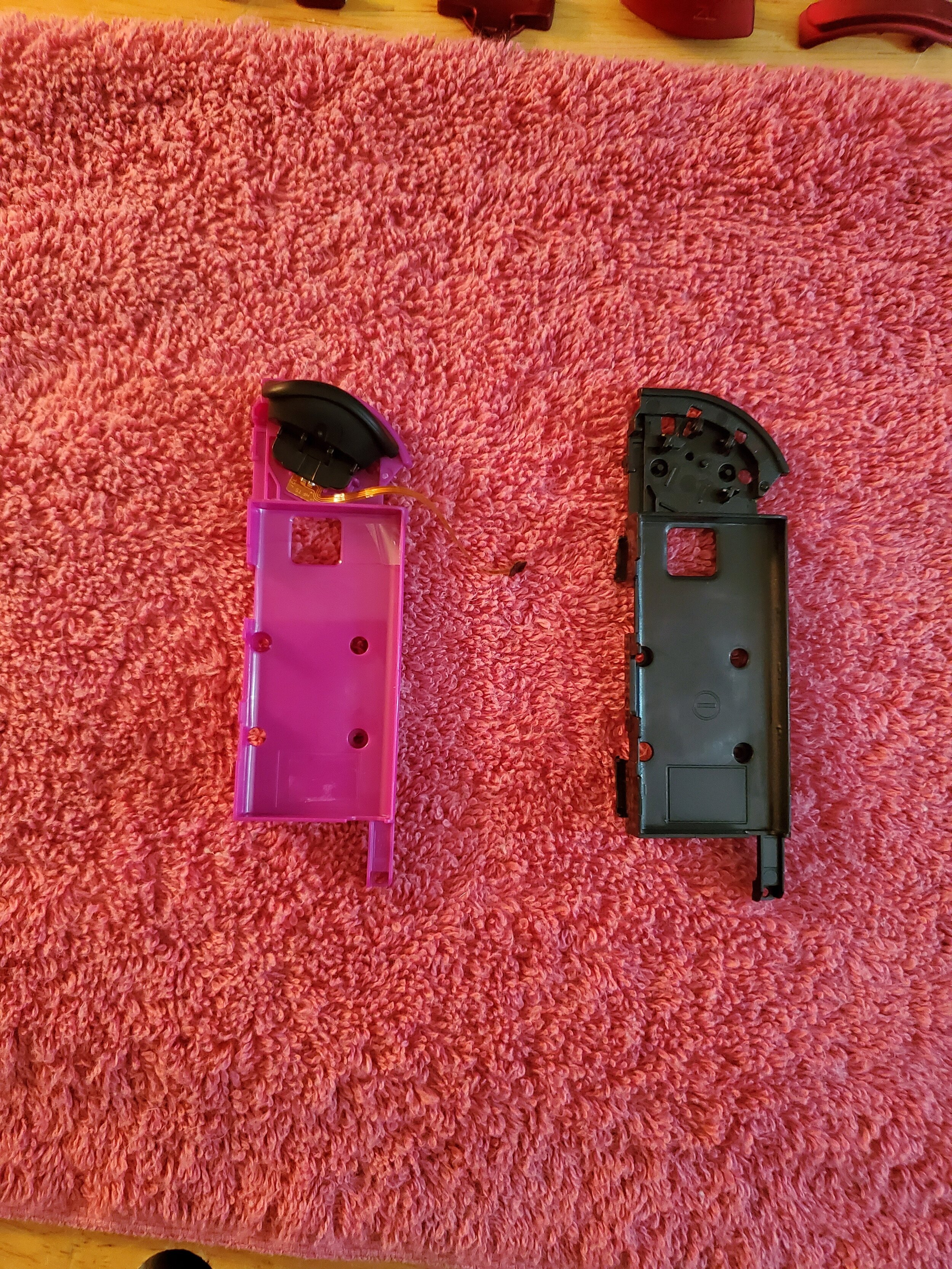
4: Left Joy-Con
In my opinion this next step is the hardest part, so let’s go ahead and get it out of the way!

5: Left Joy-Con
Remove the ZL trigger by lift the end with the springs up away from the button board, and pulling it away from the spot where the battery sits. Keep that end up so as not to break the button!

6: Left Joy-Con
Remove the single screw holding the ZL button board in place and move it over to the new battery tray, replacing the screw.

7: Left Joy-Con
Carefully mount the new ZL trigger by setting the two springs and gently reversing the motion you used to remove it.

8: Left Joy-Con
Prepare to remove the rail.

9: Left Joy-Con
Remove the rail by unscrewing the phillips head screw at the top of the shell. Go ahead and prepare your replacement SL and SR buttons, and set aside the release button once the rail is removed.

10: Left Joy-Con
Take note of the location and orientation of the old SL and SR buttons. The replacement buttons will need to mount in the same place and direction as the old (I just take a picture to use as a reference).

11: Left Joy-Con
Remove the phillips head screws holding the SL and SR button board in place with the rail. Remove the rubber inserts from the old buttons.

12: Left Joy-Con
Insert the rubber inserts to the replacement SL and SR buttons, then slide them into their corresponding places in the rail. Remember to reference your notes from earlier! Verify the sync button has not fallen out.

13: Left Joy-Con
Reassemble the SL and SR board to the rail using the two phillips head screws you just removed. Verify the orientation and location of the new buttons are accurate. Give them a press or two to confirm the buttons are making contact with the board. You should feel a click when pressing all three buttons.

14: Left Joy-Con
Insert the release button into the new shell then install the rail using the philips head screw used to remove it. There are notches on the release that should lock in place with a lever on the rail.
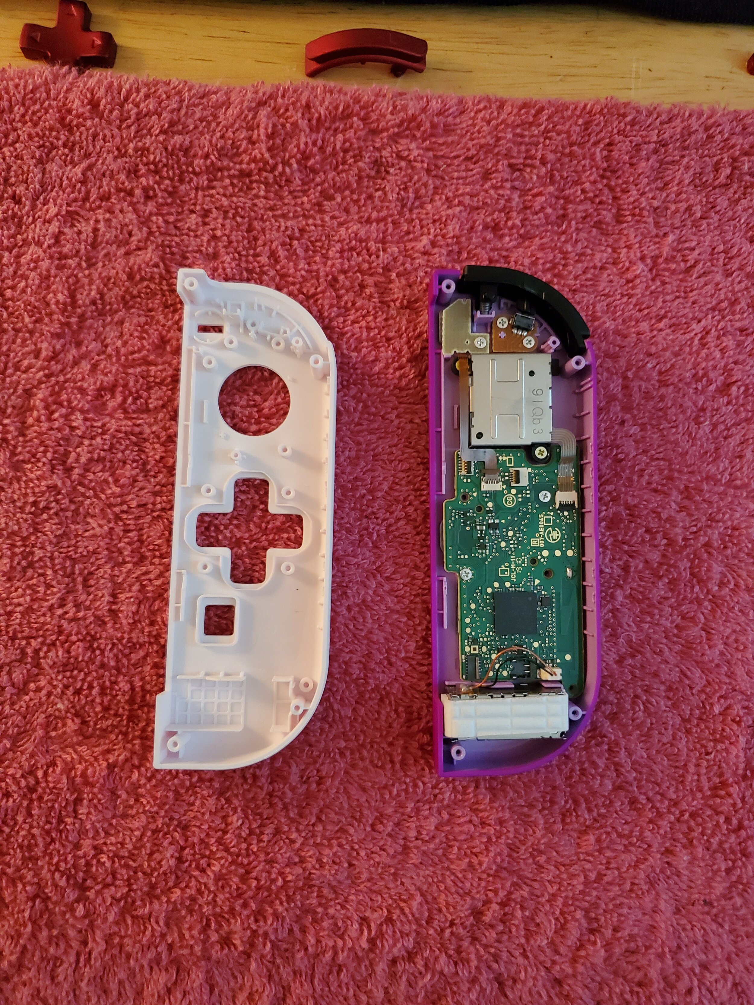
15: Left Joy-Con
Next we will be moving the other internal components to the new shell.

16: Left Joy-Con
Remove the thumbstick by unscrewing the two phillips head screws holding it in place. Remember to keep these screws organized for future steps.
Slide the L button out of the old shell. Some replacement buttons come with a spring, but just in case remove the spring and keep is somewhere safe.

17: Left Joy-Con
Unscrew the phillips head screws holding the - and L button board in place. You should have already released the ribbon from the lock in the previous steps, but just in case you missed it do so now. Remove the - Button and rubber insert from the shell.

18: Left Joy-Con
Insert the - button and pad into the new shell.
Move the - and L button board over to the new shell, replacing the screws you just removed.

19: Left Joy-Con
Gently pry the rumbler (white rectangle) out of the housing on the shell. There should only be a little bit of adhesive holding it in place. It is optional to unplug the connector from the board, but as long as you are gentle with it you don’t really have to.
Next unscrew the phillips head screws holding the board in place. Gently lift the board out of the shell and set it aside. The four directional buttons and the capture button may come up with the board, along with their corresponding rubber pads.
Set all components out neatly, remember to stay organized!

20: Left Joy-Con
Use tweezers to gently pry the black ring (where the thumbstick would mount) out of the old shell and place it in the new shell. There should be a small amount of adhesive underneath.
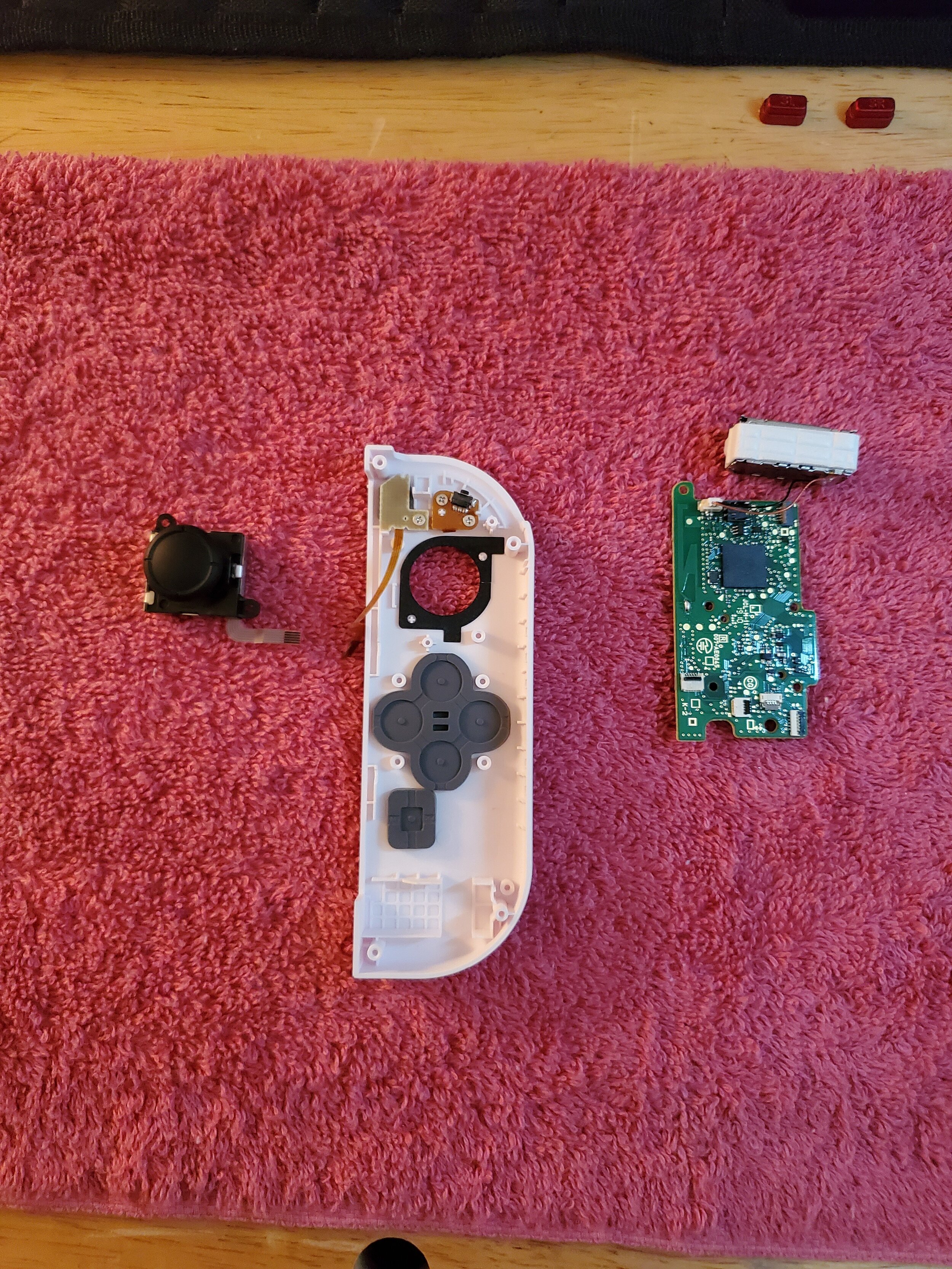
21: Left Joy-Con
Drop your new directional buttons (or D-Pad in my case) and cover with the rubber pad. There should be a small lip on the shell for the pad to slip over.
Do the same for the home button.

22: Left Joy-Con
Install the board into the new shell using the same phillips head screws you removed earlier. Gently press the rumbler back in place, being mindful of the cable and connector. If you opted to remove the connection to the board, reinsert it now.

23: Left Joy-Con
Before moving on, flip your shell over and test out the buttons. The directional buttons, home button, and - button should all click slightly when pressed.

24: Left Joy-Con
Install the thumbstick into the new shell, using the same two phillips head screws as before.

25: Left Joy-Con
Once again, flip that shell over and give it a test. Make sure the joystick is secure when clicking it in and moving the stick in all directions.
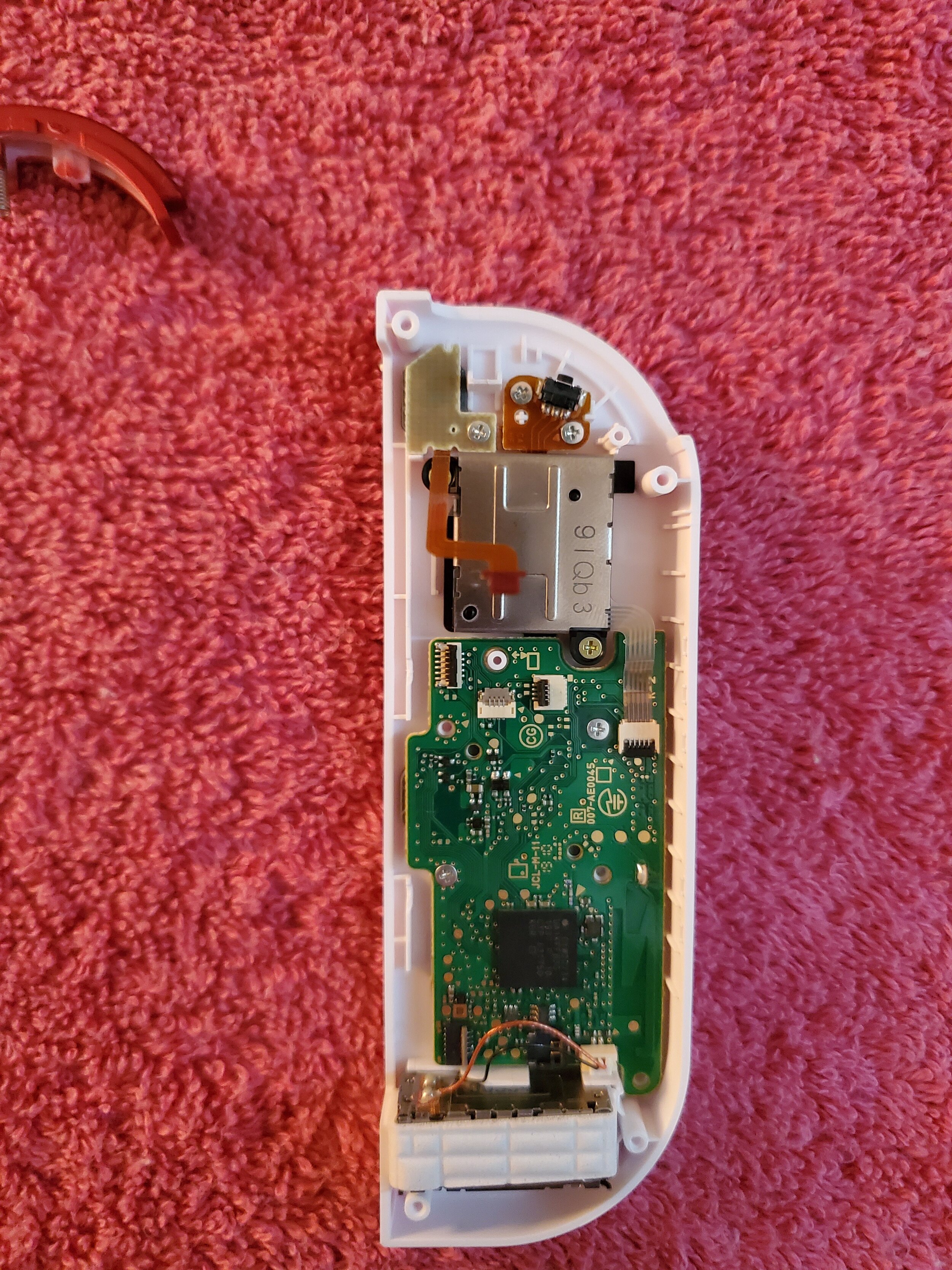
26: Left Joy-Con
Attach the ribbon cable from the joystick to the board (top right).

27: Left Joy-Con
Attach the two ribbon cables from the SL and SR button board to their corresponding headers (top left and bottom left).

28: Left Joy-Con
Reattach the - and L button board ribbon cable back to its header (just to the right of the top header you attached the SL and SR board to).

29: Left Joy-Con
Attach the ZL button board ribbon cable to the last remaining header (just to the right of the - and L button board ribbon).

30: Left Joy-Con
Slide your L button into place at the top of the shell. There should be a small insert for the spring on both the button and the shell. Keep an eye on this L button for the rest of this phase, I found it likes to slide out when you are working.

31: Left Joy-Con
Grab your new battery tray (with your new ZL trigger) and screw it down using the same screws you removed in step 2.

32: Left Joy-Con
Drop the battery into the tray and reconnect it to the main board by gently pressing down on the connector with a pair of tweezers.

33: Left Joy-Con
Gently close the two sides of the shell together, be mindful of any cables that try to pop out the sides. Be gentle, don’t smush cables.

34: Left Joy-Con
Finish this bad boy up by screwing it down with the same screws you removed in step 1.

35: Left Joy-Con
Flip it around a few times, look for anything that doesn’t look like it is lined up good.

(Complete) Left Joy-Con
The Left Joy-Con is complete. Go ahead and try to use it on your switch, test every button and make sure they work.
Now go grab some water or a snack, then let’s move on to the Right Joy-Con.

1: Right Joy-Con
The Right Joy-Con is very similar to Left, with a few extra pieces and slightly shorter ribbon cables. Your experience with the Left Joy-Con should help you out with this one.
Start by unscrewing the four triscrews on the back and gently pry the shell apart.

2: Right Joy-Con
You should now notice the extra pieces, being the Antenna (tucked along side the battery) and the infrared sensor (located at the bottom of the shell).

3: Right Joy-Con
Remove the battery the same way you removed it from the Left Joy-Con. With a pair of tweezers, remove the Antenna from the board (the terminal should be right next to the battery terminal).

4: Right Joy-Con
Remove the battery tray just like you did on the Left Joy-Con. Remember to set these screws aside for reassembly.
Gently release the grey and black latches securing ribbon connectors to the board (tweezers are your friend), with the exception of the two at the bottom left of the board (just above the rumbler).

5: Right Joy-Con
Here we go again. The good news is, the process is identical (but mirrored) to the Left Joy-Con. The bad news is, this is (in my opinion) the second hardest part of the Right Joy-Con.
Carefully remove the ZR trigger.

6: Right Joy-Con
Unscrew the phillips head screw holding the ZR button board in place.

7: Right Joy-Con
Install the ZR button board in place using the same screw you just removed.

8: Right Joy-Con
Install your new ZR trigger, following the same motion as reassembly from the Left Joy-Con.
Be slow and gently, don’t break that button off the board!

9: Right Joy-Con
You’ve seen this before, right? Lets do it again!
We will be removing the rail next.

10: Right Joy-Con
Remove the phillips head screw holding the rail in place, and set it aside. Keep the release button near by as well.
11: Right Joy-Con
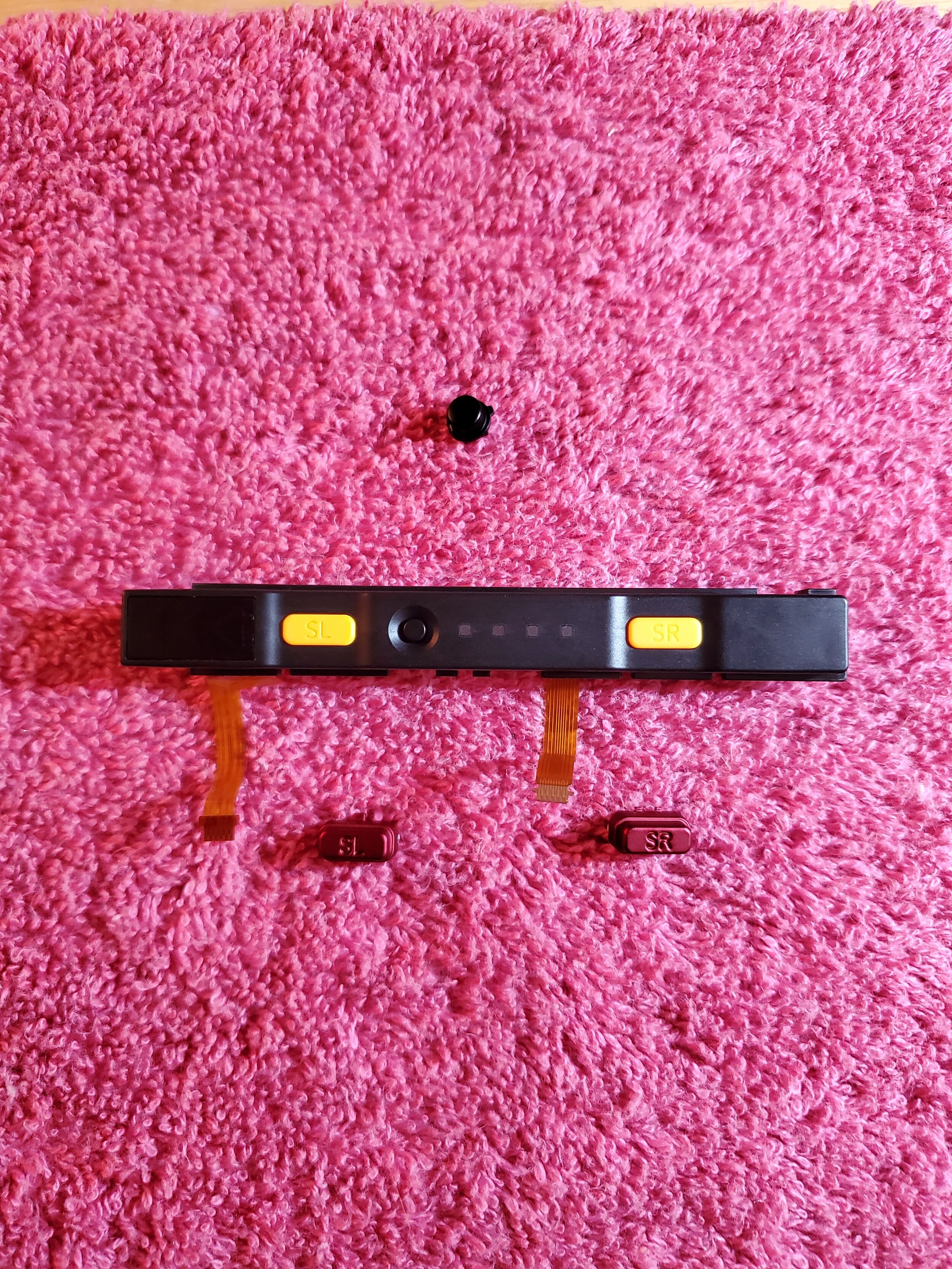
Take note of the SL and SR button orientation and position for reference in the next few steps.

12: Right Joy-Con
Repeat the same process of removing the two screws holding the SL and SR button board to the rail. Remove the old SL and SR buttons, remembering to pull out the rubber inserts. Leave the sync button in place.

13: Right Joy-Con
Insert the rubber inserts into your new SL and SR buttons, and place them in the rail. The sync button should still be there.

14: Right Joy-Con
Reinstall the SL and SR button board to the rail, reusing the same two screws you removed.
Give all three buttons a press, feel for that gentle click.

15: Right Joy-Con
Install the rail to the shell using the same screw you removed earlier.

16: Right Joy-Con
This looks familiar, too, doesn’t it? We are going to be doing the exact same thing as last time, with a few alterations to where things are.

17: Right Joy-Con
Remove the thumbstick by unscrewing the two phillips head screws holding it in place. Set these aside, stay organized.
Gently lift the R button out of the shell, be mindful of that spring as it may want to shoot off across the room.

18: Right Joy-Con
Pry out the rumbler the same as before. There’s some adhesive to work against, but you should be able to get it.

19: Right Joy-Con
Remove the remaining screws holding the main board in place, set those aside as well.
Gently start lifting the board up. You should see a black frame just below the board, as well as a connection to the infrared sensor. Gently alternate prying the corners of the frame and sensor up. Again, there is adhesive working against you, but you’ll get it out eventually, just be patient and gentle.
You should see the A, B, X, and Y buttons, the Home button, and the + button with their corresponding rubber pads now. Remove them all and set them aside.

20: Right Joy-Con
Grab some tweezers and move that black ring from where the thumbstick mounts over to the new shell. Surprise, there will be some adhesive underneath.
Take your new A, B, X, and Y buttons and insert them into the new shell (remember to be mindful of their position and orientation). Place the rubber pad over the buttons.
Next take the + button and insert it into the new shell, and place its rubber pad over the button.
Lastly grab that home button, put it in place, and slap that clear pad on top of it.
All of these pads should fit (actually sort of loosely) onto a lip on the shell.

21: Right Joy-Con
You’re almost done (In terms of counting steps)!
Move your board assembly over into the shell, reversing the process used to remove it.
Black frame with Infrared sensor in first, then the board (with screws), then the rumbler. Don’t force the rumbler in place, if it isn’t fitting try adjusting the infrared sensor. They are designed to fit like Tetris pieces.

22: Right Joy-Con
Flip it over, and take a look at all your buttons. Make sure A, B, X, and Y buttons are in the correct place.
Now give them all a press and feel for that familiar click before moving on.

23: Right Joy-Con
Mount your thumbstick using the same two screws you removed earlier. Attach the ribbon cable back to the main board (header with black latch at top left as shown in picture).

24: Right Joy-Con
Once again, flip that bad boy over and feel the thumbstick. Make sure it points in all directions and can click in without too much trouble.

25: Right Joy-Con
Reattach the SL and SR board ribbon cables to the mainboard (the two ribbon headers on the right side of the board, as shown in the picture).

26: Right Joy-Con
Remember back in step 5 when I said there was bad news? This is the part I am talking about. In my opinion this was the most frustrating part of the entire project. The goal is to get that short tiny little ribbon cable from the ZR button board fixed to the main board at the top left (as shown in picture). The small length of the cable makes it very awkward to get your tweezers in there to slide the connector in place.
If you don’t get it first try, don’t stress out. I am there with you, friend. This part (in my opinion) was just as frustrating as threading a tiny needle.
Keep working at it, you’ll get it eventually!

27: Right Joy-Con
You’re on the final stretch! The rest of the process is a piece of cake compared to step 26.
Now its time to slip that R button in place. It works the same as it did on the Left Joy-Con, just line up the spring and slide it down gently.

28: Right Joy-Con
Fold the battery tray over and secure it to the shell using the same screws you removed earlier.
29: Right Joy-Con
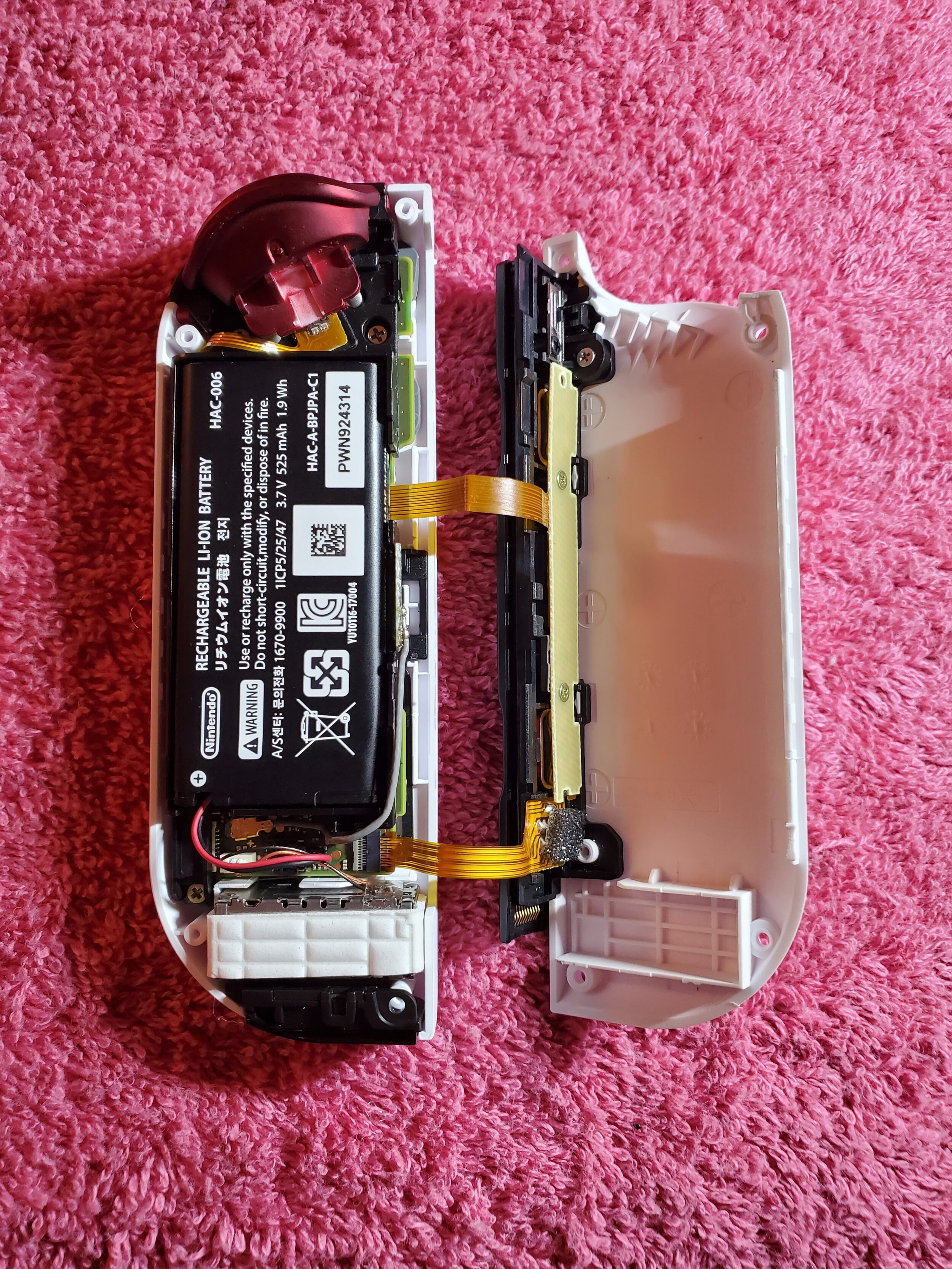
All that is left is to attach the Antenna and battery. I found it easier to attach the battery first, then the Antenna.
30: Right Joy-Con
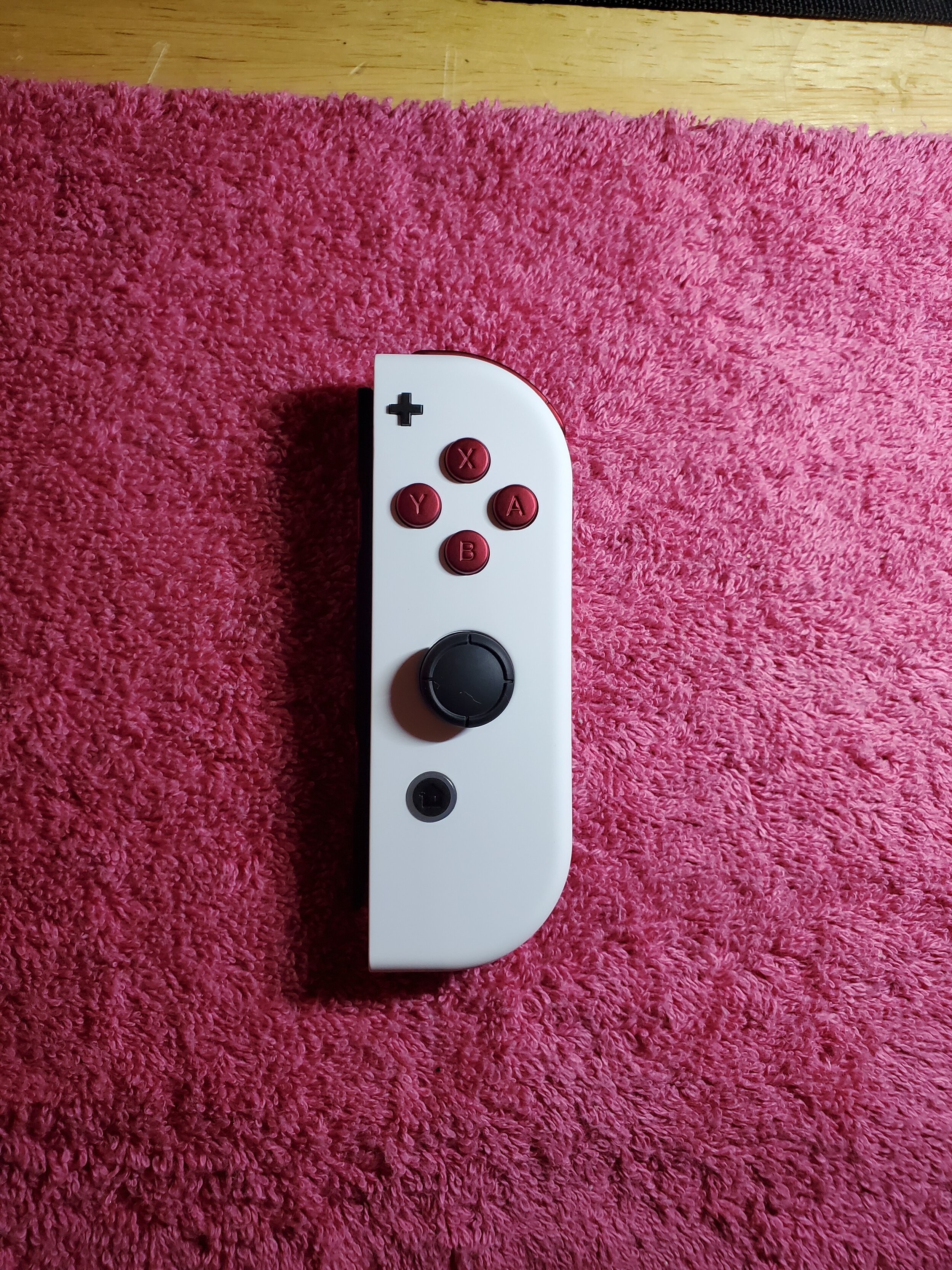
Lets wrap this up, flip that front cover over and close it against the back. The shells should line up evenly without any cables or components hanging out. Be gently, go slow, press firmly once everything is lined up.

31: Right Joy-Con
Flip it over and secure the triscrews in place.

32: Right Joy-Con
Do one last look around the Joy-Con, make sure nothing is halfway sticking out, all the buttons press without too much resistance, and no screws were left around your workspace.

(Complete) Right Joy-Con
The Right Joy-Con is complete. Go ahead and try to use it on your switch, make sure you test every button and confirm everything is working.


Cool Down: Admire your work
Take a breather, dust off your hands and take a look at what you just did. You just added a touch of personality to your device, feels good doesn’t it?
You may have noticed when you went to test out your Joy-Cons that the Shells and Buttons are still the same color as they used to be on your Switch. Fear not, for there is another guide to help you program your Joy-Cons to reflect the correct colors on your switch, the link to that guide is listed below:
Nintendo Switch: Joy-Con ToolKit Color Tweaking
Thank you for your time, and if you liked this guide please consider sharing it with someone who can benefit from it!
